Now Reading: Comprehensive Guide to UML Activity Diagrams and Business Process Modeling
-
01
Comprehensive Guide to UML Activity Diagrams and Business Process Modeling
Comprehensive Guide to UML Activity Diagrams and Business Process Modeling
1. Introduction to UML Activity Diagrams
UML (Unified Modeling Language) activity diagrams are powerful tools for visualizing workflows, business processes, and complex algorithms. They are particularly effective at illustrating both sequential and parallel activities, making them ideal for modeling dynamic systems. Activity diagrams help stakeholders understand the flow of activities, identify potential bottlenecks, and optimize processes.
2. Key Notation and Elements
Activity diagrams use a standardized set of symbols to represent various components of a process:
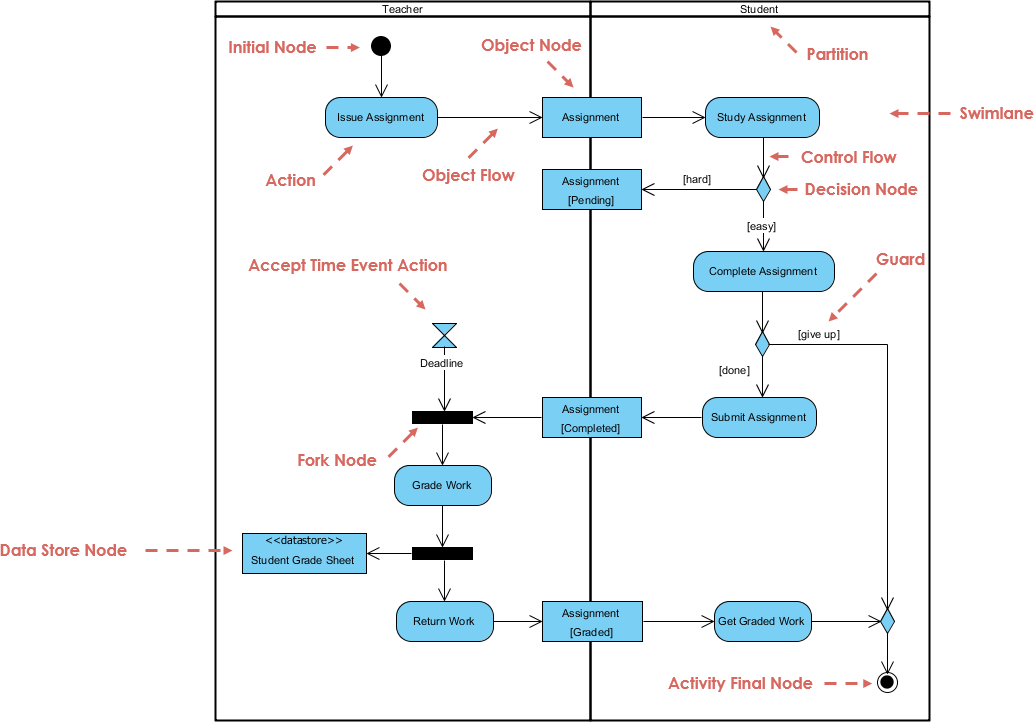
- Action Nodes: Represented by rectangles, these indicate specific tasks or actions within the process (e.g., “Verify Payment”).
- Control Flows: Arrows that show the sequence in which actions are performed.
- Forks/Joins: Used to split or merge parallel paths. Forks indicate where a process splits into multiple parallel paths, while joins indicate where parallel paths converge.
- Object Nodes: Represent data or objects that move through the system (e.g., a parcel in a shipping workflow).
- Partitions (Swimlanes): Divide activities by roles or responsibilities (e.g., “Customer,” “Driver”) to clarify who is responsible for each action.
3. Applications in Business Process Modeling
Business Workflow Visualization
Activity diagrams are particularly useful for visualizing complex business workflows involving multiple parties. For example, a parcel shipping company can use activity diagrams to:
- Map interactions between customers, drivers, and internal systems.
- Identify inefficiencies, such as redundant steps in delivery routes.
- Explore optimizations visually, such as parallelizing tasks to improve efficiency.
Data Flow Modeling
Activity diagrams can also be used to model data flow within a system. They can replace traditional Data Flow Diagrams (DFDs) by illustrating both control flow and data flow. Object nodes can show how data (e.g., inventory records) moves between actions.
4. Guidelines for Effective Modeling
- Start High-Level: Begin with a simplified “Level 0” diagram to outline major steps (e.g., “Receive Order” → “Ship Order”). Expand details in sub-diagrams using the rake notation to drill into subtasks.
- Consistent Abstraction: Ensure actions in the same diagram share a similar level of granularity. Avoid mixing high-level actions with detailed subtasks in the same diagram.
- Leverage Partitions: Use partitions to clarify role-specific tasks in multi-actor processes. This helps to separate actions performed by different roles or departments.
5. Advanced Applications
Concurrent Programming
Activity diagrams are well-suited for modeling parallel algorithms, such as:
- 3D Simulations: Using partitions to represent threads handling sub-blocks of data.
- Weather Modeling: Using forks and joins to represent simultaneous computations.
Integration with Other UML Models
- Interaction Diagrams: System operations identified in System Sequence Diagrams (SSDs) can be mapped to actions in activity diagrams.
- Class Diagrams: Object nodes in activity diagrams often correspond to domain classes in class diagrams (e.g.,
ProductDescriptionin a retail system).
6. Comparison with BPMN
While activity diagrams are powerful, they differ from BPMN (Business Process Model and Notation) in several ways:
| Feature | Activity Diagrams | BPMN |
|---|---|---|
| Audience | Technical teams (developers, architects) | Business analysts, stakeholders |
| Focus | System workflows and data flow | End-to-end business collaboration |
| Notation Complexity | Simpler (actions, forks) | Richer (events, gateways, pools) |
When to Choose:
- Activity Diagrams: Use for technical workflows, software design, or integrating with other UML models.
- BPMN: Use for cross-departmental business processes requiring detailed event and rule modeling.
8. Example: Parcel Shipping Process
Consider a parcel shipping process:
- Customer Submits Order: This action triggers the “Process Order” action.
- Parallel Tasks: The process forks into “Prepare Shipment” (warehouse) and “Generate Invoice” (billing).
- Data Flow: Object nodes track parcels and invoices until a join merges the paths for final delivery.
9. Conclusion
UML activity diagrams are indispensable for modeling workflows, optimizing processes, and bridging technical and business perspectives. By adhering to guidelines such as high-level abstraction and partition usage, teams can streamline communication and drive efficiency. While activity diagrams complement BPMN in certain contexts, their strength lies in their integration with the UML ecosystem and their ability to provide technical clarity.
References
-
Reference to Diagrams, Shapes, and Model Elements
- This guide explains how to attach additional references to shapes and diagrams in Visual Paradigm, allowing users to open and view inserted references. It also covers the use of the Diagram Hierarchy view to understand the relationships between diagrams and sub-diagrams.
- Reference to Diagrams, Shapes, and Model Elements 1
-
Resource Referencing in Visual Paradigm
- This resource provides an overview of how to add and manage references in Visual Paradigm, including linking to internal and external materials such as shapes, diagrams, files, and URLs. It also discusses the use of sub-diagrams to describe model elements in detail.
- Resource Referencing in Visual Paradigm 2
-
How to Draw Activity Diagram?
- This step-by-step guide walks users through the process of creating a UML Activity Diagram in Visual Paradigm. It covers the basics of activity diagrams, including control flow, concurrency, branching, and the use of swimlanes for partitioning actions based on participants.
- How to Draw Activity Diagram? 3
-
Free Activity Diagram Tool
- This resource introduces a free online tool for creating professional UML Activity Diagrams. It highlights features such as precise shape positioning, formatting options, and cross-platform support.
- Free Activity Diagram Tool 4
-
Activity Diagram in Visual Paradigm
- This guide provides a comprehensive overview of how to create activity diagrams in Visual Paradigm. It covers the basics of activity diagrams, including control flow, concurrency, branching, and object flow.
- Activity Diagram in Visual Paradigm 5
-
Reference to Resources in Visual Paradigm
- This guide explains how to add references to nodes in Visual Paradigm, allowing users to link to both internal and external resources such as shapes, diagrams, files, and URLs.
- Reference to Resources in Visual Paradigm 6
-
Process Order Activity Diagram Source: Visual Paradigm
- This resource provides a downloadable scientific diagram of a Process Order Activity Diagram created using Visual Paradigm. It is part of a publication on the role of e-commerce in increasing sales using Unified Modeling Language (UML).
- Process Order Activity Diagram Source: Visual Paradigm 7
-
Lab: Creating Activity Diagrams in Visual Paradigm
- This lab guide provides instructions on creating activity diagrams in Visual Paradigm. It covers the basics of activity diagrams and includes tips on using Visual Paradigm for UML.
- Lab: Creating Activity Diagrams in Visual Paradigm 8
-
Referencing Other Projects’ Model Elements in Visual Paradigm
- This guide explains how to reference model elements from other projects in Visual Paradigm. It covers the use of model indicators to identify referenced shapes and how to manage referenced model elements.
- Referencing Other Projects’ Model Elements in Visual Paradigm 9
- What is Activity Diagram?
- This resource provides an introduction to activity diagrams, describing them as advanced flowcharts that model the flow from one activity to another. It also introduces Visual Paradigm Community Edition as a free UML tool for creating activity diagrams.
- What is Activity Diagram? 10
BPMN References
-
BPMN – A Comprehensive Guide
- URL: BPMN – A Comprehensive Guide – Visual Paradigm Guides
- Description: This guide provides an in-depth look at BPMN, including its vision, evolution, and the four primary elements. It also includes steps to perform business process modeling and various BPMN examples.
-
How to Draw BPMN 2.0 Business Process Diagram
- URL: How to Draw BPMN 2.0 Business Process Diagram?
- Description: This tutorial covers the basics of drawing BPMN 2.0 diagrams, including choreography tasks and messages. It provides step-by-step instructions to create a business process diagram using Visual Paradigm.
-
How to Draw BPMN Diagram
- URL: How to Draw BPMN Diagram?
- Description: A step-by-step tutorial on how to draw BPMN diagrams using Visual Paradigm. It explains the different types of elements in BPMN and how to connect them using sequence flows.
-
How to Create BPMN Diagram
- URL: How to Create BPMN Diagram?
- Description: This guide explains how to create BPMN diagrams using Visual Paradigm. It covers the use of diagram templates, drag-and-drop functionality, and the Resource Catalog to complete the diagram.
-
Drawing BPMN Business Process Diagram
- URL: Drawing BPMN Business Process Diagram
- Description: This resource provides detailed instructions on how to draw BPMN diagrams using Visual Paradigm. It includes information on using the BPMN toolset and documenting business workflows.
-
How to Use Data Objects in BPMN
- URL: How to Use Data Objects in BPMN
- Description: This guide explains how to use data objects in BPMN diagrams. It covers the different types of data objects and how to attach them to sequence flows between activities.
-
Visual Paradigm BPMN
- URL: Visual Paradigm BPMN – Visual Paradigm BPMN site
- Description: This site provides resources on maintaining clear records and using BPMN diagrams for visual documentation of current and future processes, as well as illustrating gaps and action plans.
These references should provide a solid foundation for understanding and creating BPMN and Activity diagrams using Visual Paradigm.